Module 5: Gas Lift Systems
Reducing mixture density with injected gas to restore flow and optimize production.
🎯 Learning Objectives
- Explain how continuous and intermittent gas lift reduce hydrostatic head.
- Describe unloading sequence and valve behavior (IPO/orifice).
- Choose injection depth and rate based on GLR, pressure, and constraints.
- Diagnose common issues (heading, surging, erosion) and mitigations.
📘 Key Terms
GLR (gas-to-liquid)
Unloading valves
IPO valve
Orifice valve
Mandrel
Annular flow
📎 Prerequisite
Module 3 — Electrical Submersible Pumps (ESP)
ℹ️ What & Why
Gas lift injects high-pressure gas into the production string through mandrels equipped with valves. The injected gas reduces mixture density and thus the hydrostatic head in the tubing—improving drawdown and enabling sustained flow. It is flexible, tolerant of solids, and well suited to deviated and high-temperature wells.
⚙️ Principles
- Continuous lift: steady injection to reduce gradient along a designed depth.
- Intermittent lift: periodic gas slugs to lift accumulated liquid at low rates.
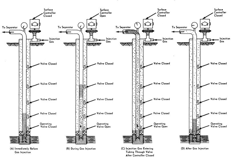
- Unloading: valves open from top to bottom as casing pressure overcomes dome pressure, moving the injection point deeper.
🧩 Components
- Surface gas source (pipeline/compressor), scrubber, regulators, and injection choke.
- Casing–tubing annulus as gas conduit; mandrels contain retrievable valves.
- Valves: IPO (injection pressure operated) for unloading; orifice for steady injection.
- Downhole packer (optional) to control flow paths and improve efficiency.
📏 Operating Considerations
💡
Field Tip
Start injection shallow and step deeper during unloading—monitor casing/tubing pressures and stabilize before moving to the next valve.⚠️
Common Pitfall
Excessive casing pressure or oversized orifice causes heading (surging). Use the smallest orifice that meets target rate and add damping at surface.🧪 Worked Example — Hydrostatic Reduction
Concept
ΔP ≈ (∇oil − ∇mix) × Depth
Given: Oil gradient ∇oil ≈ 0.36 psi/ft; with gas lift, mixture gradient ∇mix ≈ 0.18 psi/ft to 5,000 ft.
Compute: ΔP ≈ (0.36 − 0.18) × 5000 = ~900 psi reduction in hydrostatic head, increasing drawdown or WHP margin.
Actual gradients depend on GLR, P–T, slip, and composition—use detailed multiphase correlations for design.
🧭 Configuration Patterns
Principles of Operation
High-pressure gas enters the annulus and passes through valves into the tubing. The resulting gas–liquid mixture has a lower average density, reducing the pressure gradient. During unloading, the top valve opens first; as the well stabilizes, deeper valves open until the intended operating valve is reached.
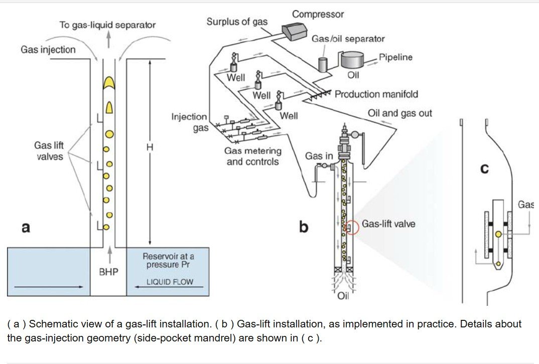
Injection Gas Lift Configuration
Typical surface equipment includes a scrubber, pressure control, and an injection choke. Gas flows down the annulus to mandrels equipped with IPO or orifice valves. The design sets valve depths and dome pressures to ensure a predictable unloading sequence and a stable operating point.
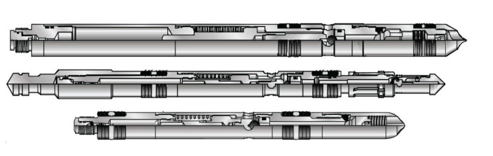
Retrievable Gas Lift Valves
Wireline-retrievable valves allow intervention without pulling the tubing. IPO valves use dome-charged bellows that open with casing pressure; orifice valves meter steady flow at the operating depth. Proper calibration prevents premature opening and erosion.
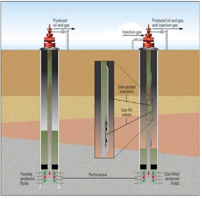
Typical Gas-Lift Installation
A representative completion includes a packer, mandrels at designed depths, and an operating valve near or below the midpoint of the liquid column. For deviated wells, spacing may be adjusted to account for holdup and friction changes.
✅ Quick Knowledge Check
1) The primary mechanism by which gas lift increases production is:
Correct — injected gas lightens the column and lowers ∇P.
2) During unloading with IPO valves, which valve opens first?
Unloading proceeds from shallow to deep as casing pressure overcomes each dome setting.
3) Spot the mistake: “Use the largest orifice possible to avoid heading.”
Right — size for the minimum stable flow that meets target rate.
🧾 Summary & Takeaways
- Gas lift reduces hydrostatic head by lowering mixture density with injected gas.
- Unloading is sequenced from shallow to deep using IPO valves; an orifice maintains steady injection.
- Design balances injection depth, GLR, and surface/completion constraints to avoid heading.
- Retrievable valves simplify maintenance and optimization without pulling tubing.
➡️ What’s Next
Up next: Module 6 — Hydraulic/Jet Pumping
Compare jet/hydraulic vs. gas lift for deep, high-temperature, or sand-handling scenarios.
Last updated: Aug 2025 • Author: Atlas ESP Academy