Module 2: Sucker-Rod Pumping Systems
Beam units, rod strings, and downhole pump mechanics.
🎯 Learning Objectives
- Explain how beam units convert rotary to reciprocating motion.
- Identify the function of the rod string and downhole pump valves.
- Estimate production rate using Q ≈ A × Stroke × SPM × Fillage × 1440 × η.
- List common operational issues (gas interference, wear) and mitigations.
📘 Key Terms
SPM
Fillage
Traveling valve
Standing valve
Polished-rod load
📎 Prerequisite
Module 1 — Intro to Artificial Lift
ℹ️ What & Why
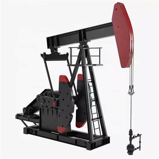
Sucker-rod systems use a surface beam unit to drive a reciprocating downhole pump. They are the most widely deployed lift method, spanning low-rate land wells to large fields, thanks to simplicity, maintainability, and cost effectiveness.
⚙️ Principles of Operation
- Beam/gearbox converts rotary motion to a vertical stroke at the polished rod.
- Rod string transmits the motion to the downhole pump barrel & plunger.
- Upstroke: traveling valve closes; fluid passes the standing valve and lifts.
- Downstroke: traveling valve opens; chamber fills for the next cycle.
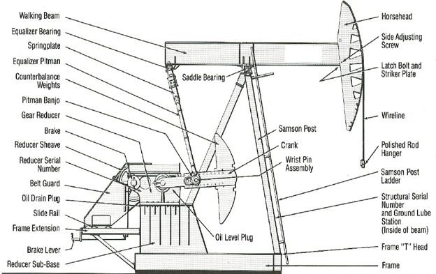
🧩 System Components
- Surface unit (beam + gearbox) and prime mover (motor/engine).
- Sucker-rod string (graded/tapered) to manage load and wear.
- Downhole pump with traveling & standing valves.
- Tubing anchor / seating nipple for pump placement.
- Wellhead & polished-rod seal for load transfer and sealing.
📏 Operating Considerations
💡
Field Tip
Start with moderate SPM and tune for fillage & efficiency before increasing rate.⚠️
Common Pitfall
Ignoring gas interference at the pump intake reduces fillage and increases loads.
Add separation strategies where needed.🧪 Worked Example — Estimating Rate
Formula
Q ≈ Aplunger × Stroke × SPM × Fillage × 1440 × ηvol
Given: Plunger Ø = 1.5 in → A = 1.767 in²; Stroke = 100 in; SPM = 8; Fillage = 0.85; ηvol=0.9.
Compute: Q ≈ 1.767 × 100 × 8 × 0.85 × 1440 × 0.9 / 231 ≈ ~850 bpd (approx.).
231 in³ = 1 gallon; 42 gal = 1 bbl. Use detailed corrections for slip/compressibility in practice.
Tip: Click any figure to open the full-size image in a new tab.
✅ Quick Knowledge Check
1) Which component converts rotary to reciprocating motion?
The surface beam + gearbox provides the reciprocating stroke.
2) Low pump fillage is most commonly due to…
Gas at the intake reduces effective intake volume; separation helps.
3) Spot the mistake (Worked Example): Which change most directly increases Q?
Q scales with SPM and stroke while fillage & efficiency remain high.
🧾 Summary & Takeaways
- Beam/gearbox creates a reciprocating stroke that drives the downhole pump.
- Traveling/standing valves control intake and lift across strokes.
- Rate scales with A, stroke, SPM, fillage, and volumetric efficiency.
- Watch for gas interference, deviation wear, and excessive loads.
- Tune SPM and separation first; then optimize rod design and pump size.
➡️ What’s Next
Up next: Module 3 — Electrical Submersible Pumps (ESP)
Recommended: skim a vendor beam-pump manual; review your field’s SPM/fillage trends.
Last updated: Aug 2025 • Author: Atlas ESP Academy